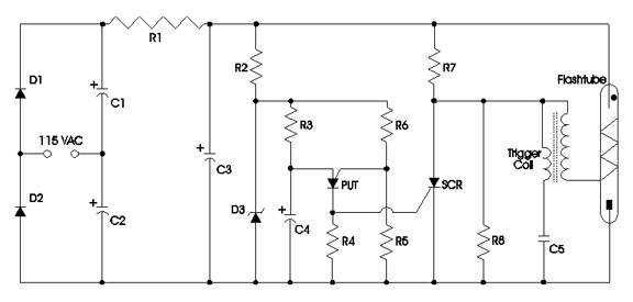
D1, D2, C1, and C2 double the AC line in, charging C3 through R1 to approximately 320 volts. R1 isolates the voltage doubler from the discharge capacitor C3 so that C1 and C2 do not participate in the flashtube discharge path. R2 and D3 form a 16-volt supply for a relaxation ocillator from parts R3, R4, R5, R6, C4, and the PUT. This gates the SCR at approximately 60-70 times each minute, which discharges C5 through the primary of the trigger coil, thereby triggering the flashtube. R7 and R8 form a volt age divider to keep the voltage within safe limits for the SCR and C5. The flash energy produces 320 x 320 x .0001 x .5 = 5.12 joules.
For further information or comments, contact:
Cadance Anderson --
tukwilacady@gmail.com
Return to Cadance's Home Page
This page last updated on March 28, 1998.