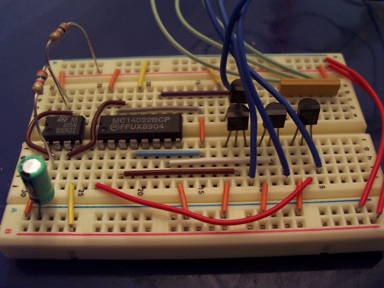
The final circuit looks much like this prototype, but has room for a fifth driver FET and avoids some of the non-orthogonal jumper wires. Building the final circuit, I actually had to be careful to not use too many of the same tie wires, because every wire I used would need to be multiplied 17 times. The 555 (on the right) provides a clock for the 4022, a divide-by-8 counter which produces a 1-of-8 output. I tuned the clock to be about 1 Hz and reset the 4022 on bit 6 (so it cycles through exactly five outputs). The FETs switch the LEDs. I originally thought the 4022 could drive the LEDs directly, but was proven wrong very quickly. Thanks, Dad, for the tip about using the FETs. 8)
(Click the image to view a larger version.)